The Radio Transmitter
Transmitter Block Diagrams

In the transmitter block diagram shown, the "oscillator"
-
is variable in frequency
-
generates an audio frequency tone during tests
-
Correct Answeruses a crystal for good frequency stability
-
may have a calibrated dial
Tags: none

In the transmitter block diagram shown, the "balanced modulator"
-
balances the high and low frequencies in the audio signal
-
Correct Answerperforms double sideband suppressed carrier modulation
-
acts as a tone control
-
balances the standing wave ratio
Tags: none

In the transmitter block diagram shown, the "filter"
-
removes mains hum from the audio signal
-
suppresses unwanted harmonics of the RF signal
-
Correct Answerremoves one sideband from the modulated signal
-
removes the carrier component from the modulated signal
Tags: none

In the transmitter block diagram shown, the "mixer"
-
adds the correct proportion of carrier to the SSB signal
-
mixes the audio and RF signals in the correct proportions
-
Correct Answertranslates the SSB signal to the required frequency
-
mixes the two sidebands in the correct proportions
Tags: none

In the transmitter block diagram shown, the "linear amplifier"
-
has all components arranged in-line
-
Correct Answeramplifies the modulated signal with no distortion
-
aligns the two sidebands correctly
-
removes any unwanted amplitude modulation from the signal
Tags: none

In the transmitter block diagram shown, the "VFO" is
-
a voice frequency oscillator
-
a varactor fixed oscillator
-
a virtual faze oscillator
-
Correct Answera variable frequency oscillator
Tags: none

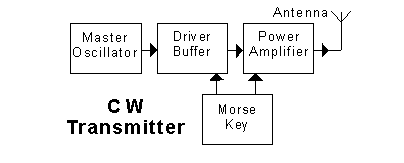
In the transmitter block diagram shown, the "master oscillator" produces
-
Correct Answera steady signal at the required carrier frequency
-
a pulsating signal at the required carrier frequency
-
a 800 Hz signal to modulate the carrier
-
a modulated CW signal
Tags: none

In the transmitter block diagram shown, the "driver buffer"
-
filters any sharp edges from the input signal
-
drives the power amplifier into saturation
-
Correct Answerprovides isolation between the oscillator and power amplifier
-
changes the frequency of the master oscillator signal
Tags: none

In the transmitter block diagram shown, the "Morse key"
-
turns the DC power to the transmitter on and off
-
Correct Answerallows the oscillator signal to pass only when the key is depressed
-
changes the frequency of the transmitted signal when the key is depressed
-
adds an 800 Hz audio tone to the signal when the key is depressed
Tags: none

In the transmitter block diagram shown, the "power amplifier"
-
Correct Answerneed not have linear characteristics
-
amplifies the bandwidth of its input signal
-
must be adjusted during key-up conditions
-
should be water-cooled
Tags: none

In the transmitter block diagram shown, the "speech amplifier"
-
Correct Answeramplifies the audio signal from the microphone
-
is a spectral equalization entropy changer
-
amplifies only speech, while discriminating against background noises
-
shifts the frequency spectrum of the audio signal into the RF region
Tags: none

In the transmitter block diagram shown, the "modulator"
-
is an amplitude modulator with feedback
-
is an SSB modulator with feedback
-
causes the speech waveform to gate the oscillator on and off
-
Correct Answercauses the speech waveform to shift the frequency of the oscillator
Tags: none

In the transmitter block diagram shown, the "oscillator" is
-
an audio frequency oscillator
-
Correct Answera variable frequency RF oscillator
-
a beat frequency oscillator
-
a variable frequency audio oscillator
Tags: none

In the transmitter block diagram shown, the "frequency multiplier"
-
translates the frequency of the modulated signal into the RF spectrum
-
changes the frequency of the speech signal
-
Correct Answerproduces a harmonic of the oscillator signal
-
multiplies the oscillator signal by the speech signal
The Frequency Multiplier stage is an RF amplifier with a tuned output - the output tuned to a harmonic of the input signal.
Last edited by cmscouler. Register to edit
Tags: none

In the transmitter block diagram shown, the "power amplifier"
-
increases the voltage of the mains to drive the antenna
-
amplifies the audio frequency component of the signal
-
amplifies the selected sideband to a suitable level
-
Correct Answeramplifies the RF signal to a suitable level
Tags: none
The signal from an amplitude modulated transmitter consists of
-
Correct Answera carrier and two sidebands
-
a carrier and one sideband
-
no carrier and two sidebands
-
no carrier and one sideband
Tags: none
The signal from a frequency modulated transmitter has
-
an amplitude which varies with the modulating waveform
-
Correct Answera frequency which varies with the modulating waveform
-
a single sideband which follows the modulating waveform
-
no sideband structure
Tags: none
The signal from a balanced modulator consists of
-
a carrier and two sidebands
-
a carrier and one sideband
-
Correct Answerno carrier and two sidebands
-
no carrier and one sideband
Tags: none
The signal from a CW transmitter consists of
-
a continuous, unmodulated RF waveform
-
a continuous RF waveform modulated with an 800 Hz Morse signal
-
Correct Answeran RF waveform which is keyed on and off to form Morse characters
-
a continuous RF waveform which changes frequency in synchronism with an applied Morse signal
Tags: none
Tags: none
View Privacy Policy | Get help with HamStudy.org™
